Circuit - user manual
Circuit has a colour-coded interface, with crossover filter and waveshape modelling elements in blue, input signal and envelope follower in red, LFO in orange, and Lorenz attractor in yellow.
A simplified schematic diagram of Diffusion's internals is presented below:
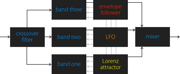
Crossover
When the sound enters Circuit, it is split into three frequency bands. The crossover frequencies between band 1 and 2 can be adjusted from 100 to 400 Hz, and between band 2 and 3 from 800 Hz to 4 kHz. This is done by vertically dragging the frequency handles with labels, located between the bands:

An on/off switch on each of the three bands defines whether it's being processed or is passed dry into the output. Band output level slider is in effect in both cases.

Signal processing
Each band lets you choose one of 12 processing models.
The first row has six different waveshape transformer algorithms which change the signal shape using sine-based transfer functions and make the sound very synthetic:

Non-linear distortion turns the signal into a square wave:

Foldback distortion warps the signal into a harsh-sounding waveform:

Circuit-bent low-pass filter produces an extremely raw, buzzing sound:

Sample rate reduction resamples the signal at a rate of 100 Hz to 22 kHz:

Bit depth reduction changes the bit depth of the signal from 12 to 1 bit:

Ring modulator multiplies the signal with a sine wave with frequency from 50 Hz to 5 kHz.

A waveform scope above the algorithm selector shows approximately how each harmonic partial of the sound will be changed:
The band output level is adjusted by this staircase-style slider:

The band model parameter is adjusted by this arrow-style slider:

Beneath this slider are three bipolar modulation sliders which define the parameter modulation depth from the envelope follower (red), LFO (orange) and Lorenz generator (yellow):

Input & envelope
The input level is adjusted by the staircase-style slider. It affects the character of the bands which are set to waveshape or distortion models.

The input section features an envelope follower, which detects the average energy of the input signal and allows you to use it as a modulation source. Envelope follower sensitivity is adjusted with this slider:

Envelope follower smoothness is adjusted with this slider:

LFO
The low-frequency oscillator generates a repeating modulation signal and is always synchronised to the host sequencer tempo and position. It can be set to one of four waveforms: triangle, saw, square and pulse:

The current LFO phase is indicated by a rotating arc around the rate display:

The rate can be set from as fast as 1/64 note to as slow as 4 bars, using the arrow-style slider:

Lorenz attractor
Lorenz attractor is a dynamic chaos system typically used for modelling the flow of air. It generates a continuous signal which is smoothly fluctuating and never repeating. The Lorenz chaos generator's approximate output is displayed as a two-dimensional shape:

It has a variable rate which is adjusted using this slider: